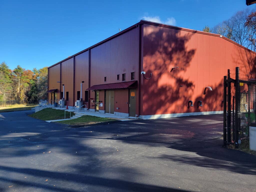
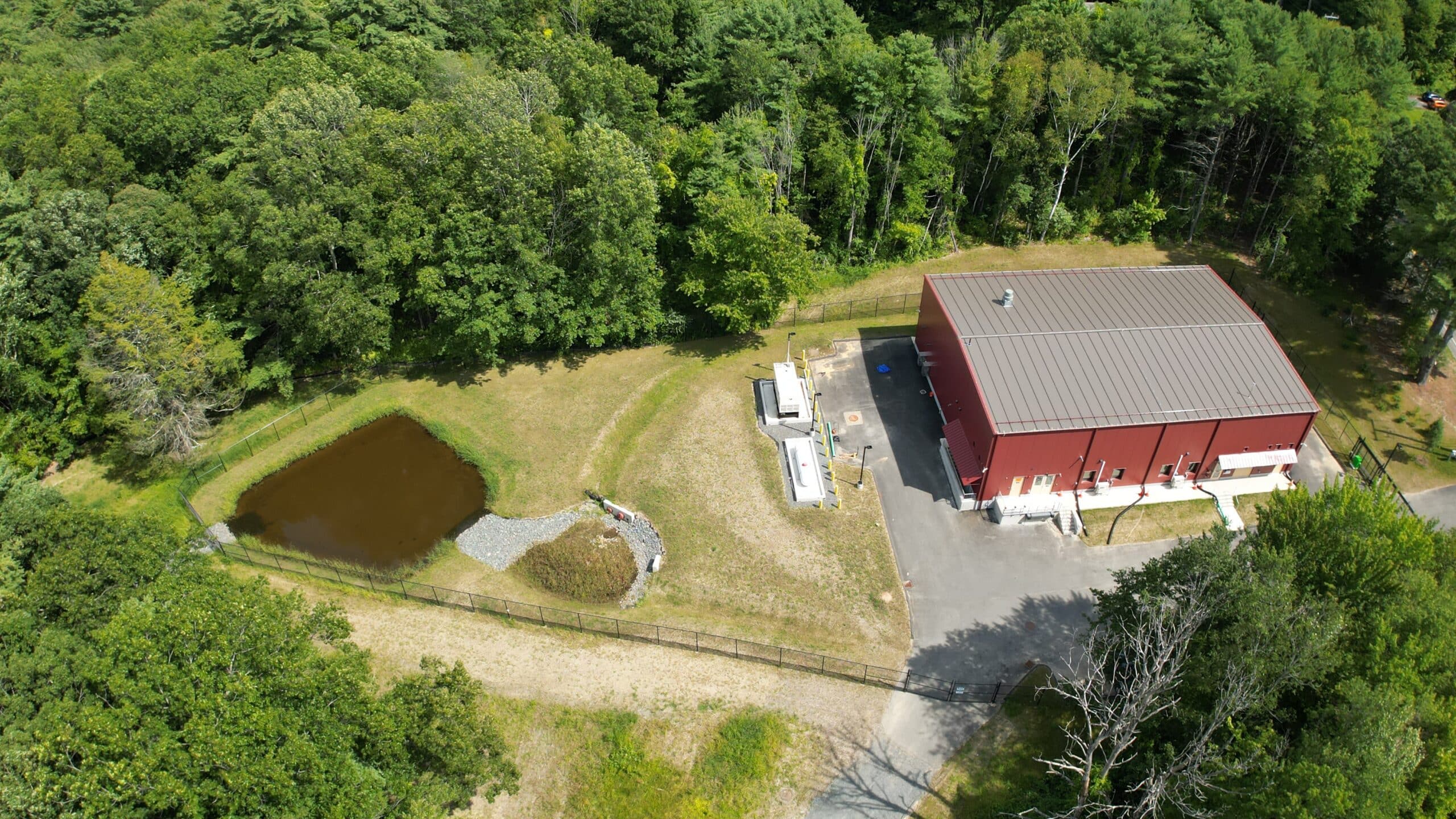
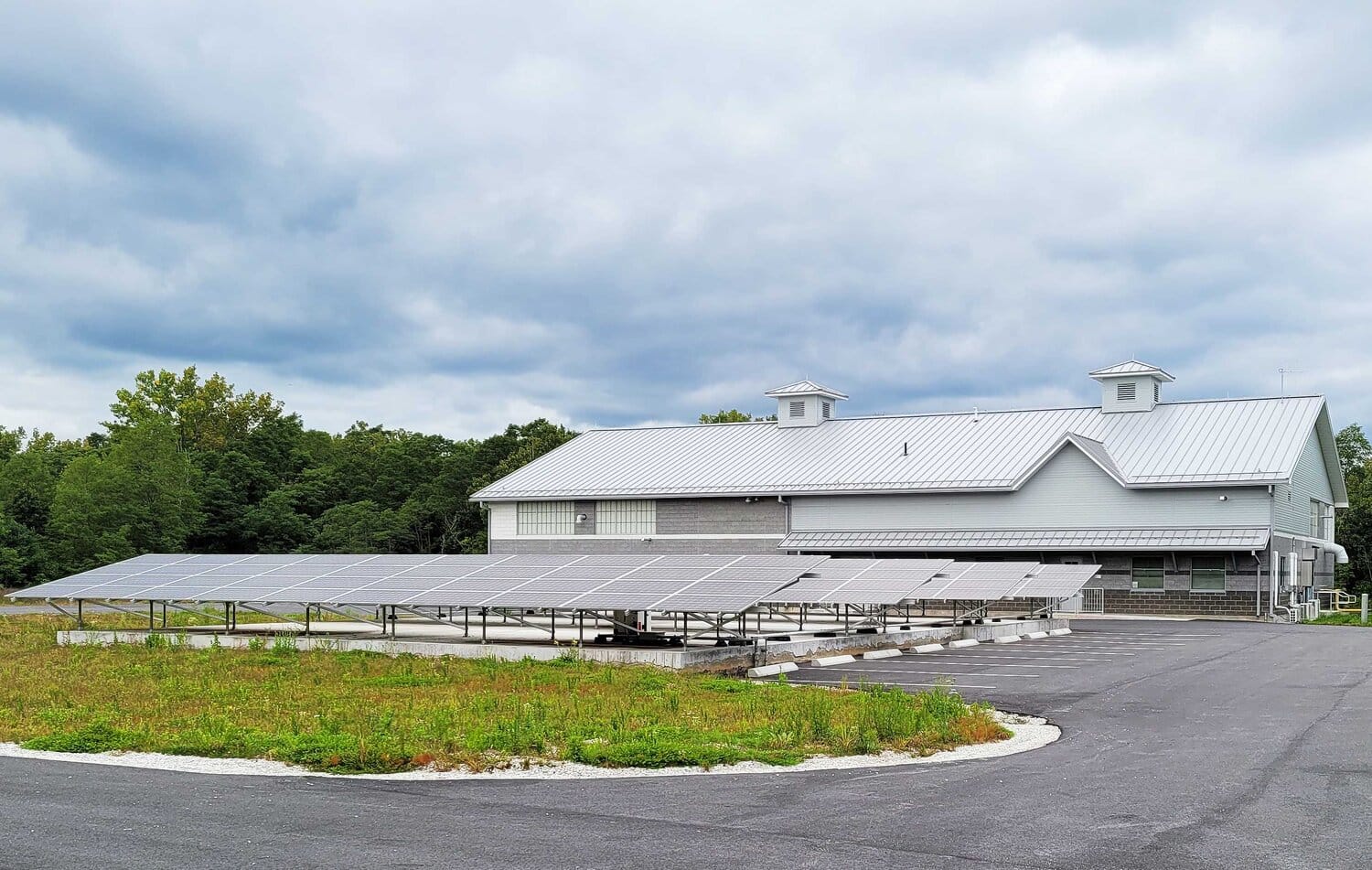
 Tata & Howard contracted with the Town of Amherst for design, permitting, bidding, and construction administration of the 1.5 million gallon per day (MGD) Centennial Water Treatment Plant (WTP) to treat surface water from the Pelham Reservoir System. The existing Centennial WTP, located in the Town of Pelham but supplying the Amherst Public Water System, has a history of issues with turbidity, color, and disinfection byproducts in the form of total trihalomethanes (TTHM) and haloacetic acids (HAA5) because of high levels of organics in the Pelham Reservoir System. Due to the age and condition of the existing WTP, the filters which were the primary treatment process at the existing WTP were no longer effective at removing organics, leading to a decrease in finished water quality and total WTP capacity. The existing Centennial WTP has been offline since 2018 due to water quality, as well as infrastructure concerns related to a lightning strike which impacted pumping equipment and communications at the Centennial Water Treatment Plant’s raw water pump station.
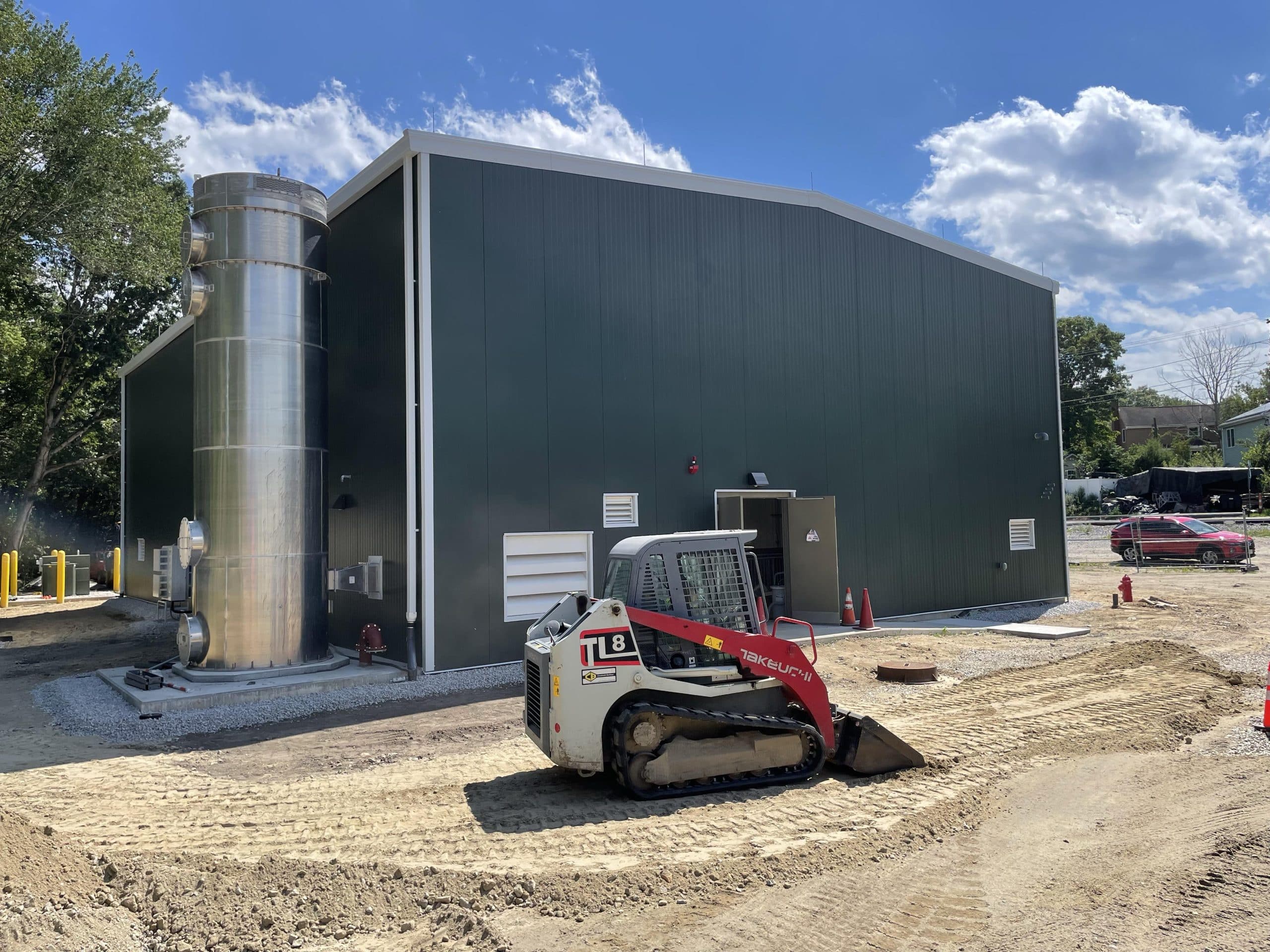
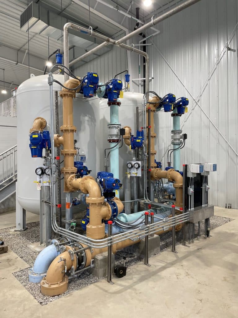
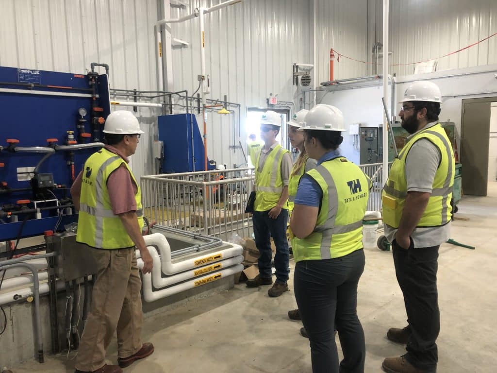
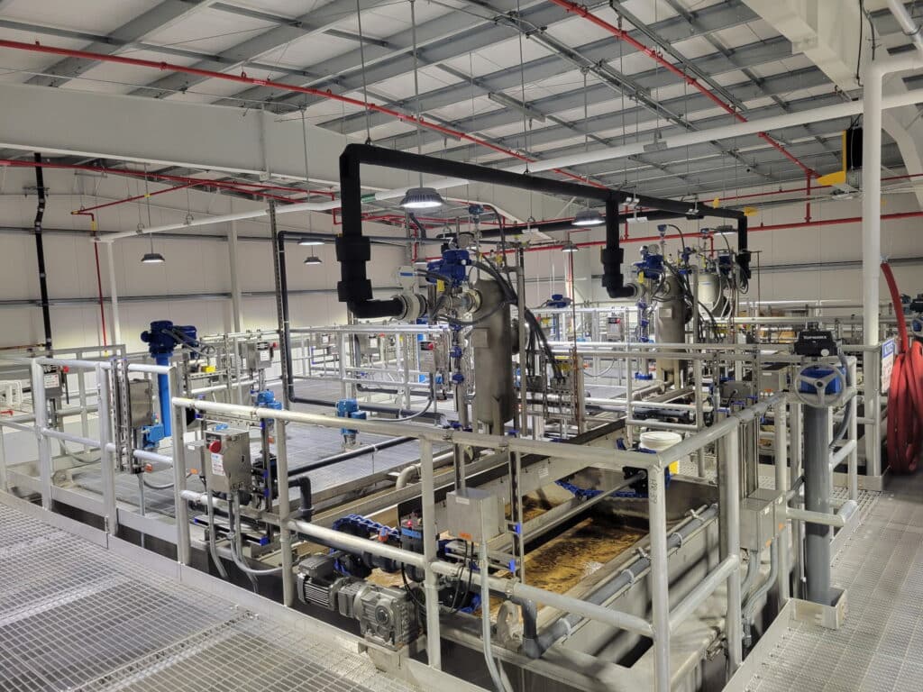
 Based on the results of the pilot study performed by the Town of Amherst, Tata & Howard completed design of the new Centennial Water Treatment Plant including dissolved air flotation (DAF) clarifiers and granular activated carbon (GAC) filtration for treatment of organics, color, turbidity, and low levels of iron and manganese. The DAF system includes polyaluminum chloride for coagulation, two rapid mix chambers, and three package DAF units which each include two high rate flocculation chambers, two low-rate flocculation chambers, a saturation tank, effluent collection system, discharge weir, mechanical skimmers and beach, and associated appurtenances and controls. Three dual media filter chambers with a silica sand/course garnet base layer and GAC above are located downstream of the DAF units, prior to final chemical addition.
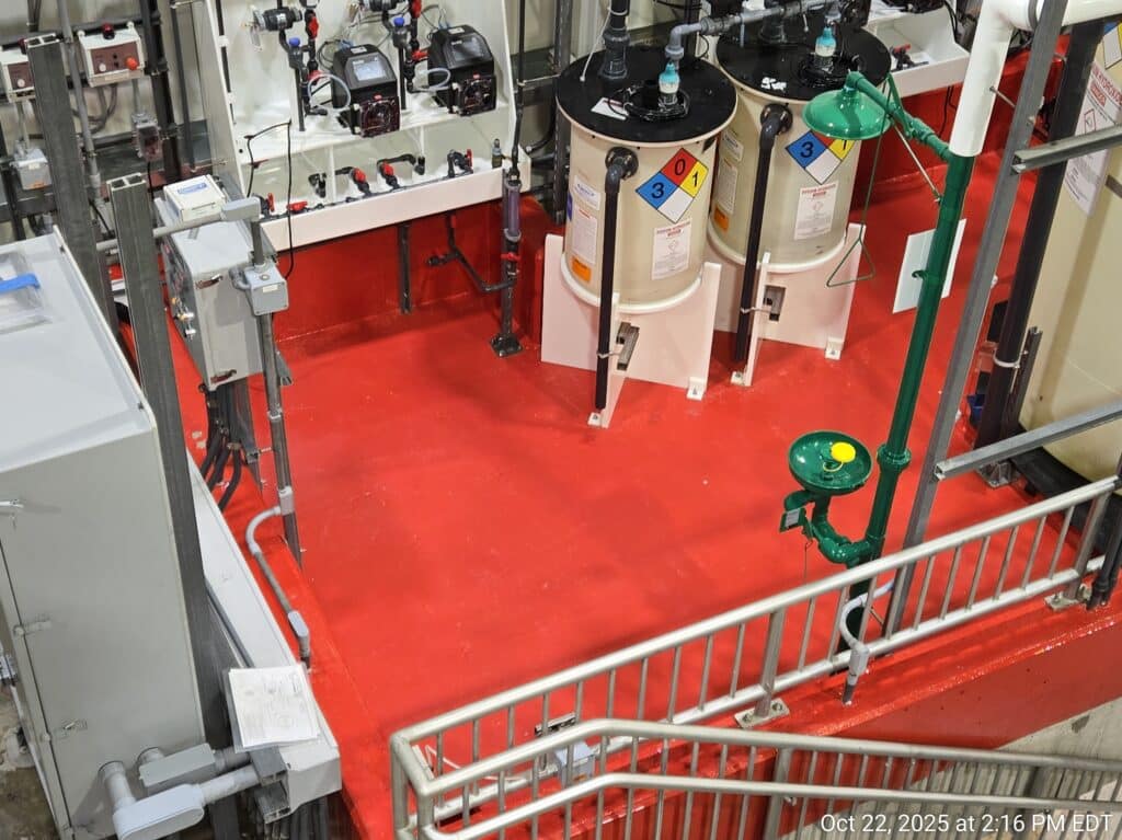
 Additional chemical feed includes a gaseous chlorine system for disinfection, gaseous ammonia for chloramine formation, sodium fluoride for dental health, and sodium hydroxide for pH adjustment and corrosion control. The new facility also includes an advanced Supervisory Control and Data Acquisition (SCADA) system for automated control of the water treatment plant. Operators for the Town of Amherst will be able to remotely monitor and control operation of the Centennial WTP, through a recently extended town fiber optic cable network.
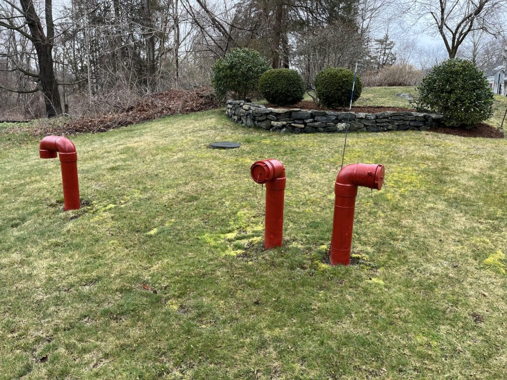
The design of the Centennial WTP included provisions to maintain the Amherst water distribution system, as even with the Centennial WTP offline, the clearwell of the existing facility also serves to maintain pressure in a small portion of the water distribution system between the Centennial WTP and a booster pump station. The Centennial WTP feeds the majority of the water system (excluding the portion between the WTP and the booster pump station) by gravity. Since the existing WTP including the clearwell was demolished prior to construction of the new WTP, design and construction of the new WTP included temporary water storage tanks to maintain pressure and keep all connections active in the high service area of the Amherst Public Water System.
Permitting for this project included a BRP WS 24 New Treatment Plant application with MassDEP, Site Plan Review with the Pelham Zoning Board of Appeals, and a Request for Determination of Applicability (RDA) with Pelham Conservation Commission.
The Centennial Water Treatment Plant was bid and awarded to R.H. White Construction Co. of Auburn, MA for a contract amount of $18,876,000, and the project received funding though the Drinking Water State Revolving Fund program. Construction was completed and a ribbon cutting ceremony was held in October 2025.

 Estimated project budgetary costs for the sewer service area collection system, pump stations, and transport to the City of Danbury along with a phasing and implementation plan were included in the final draft report to the Town of New Fairfield.
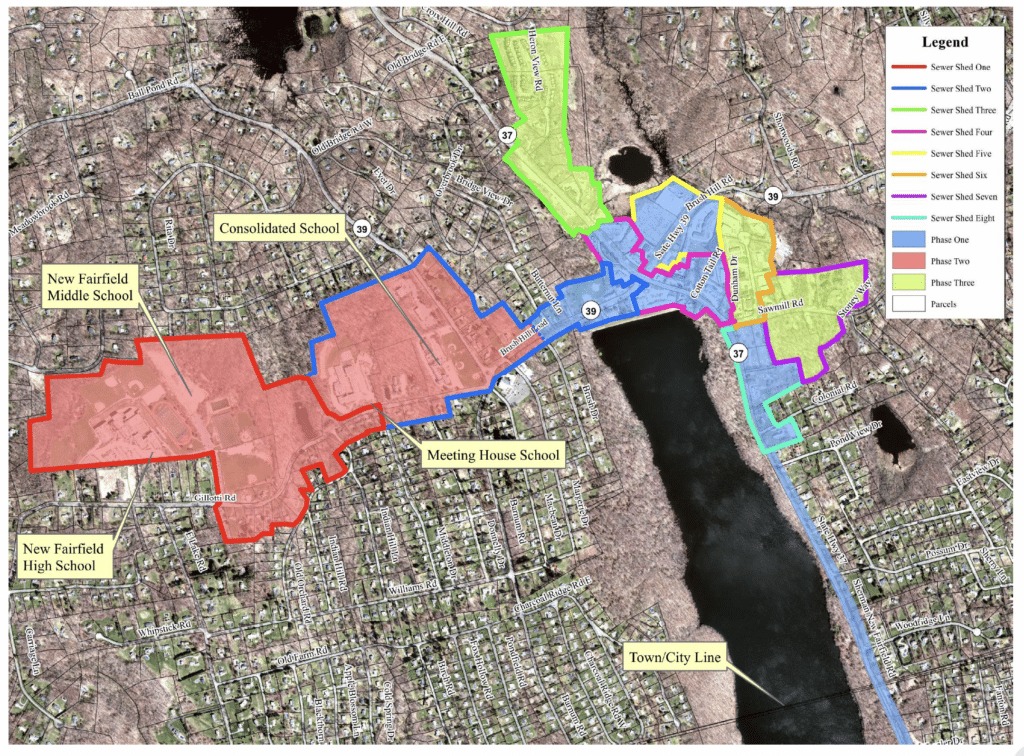 Tata & Howard provided preliminary and final design of 2.7 miles of gravity sewers, one main pump station, four remote, submersible pump stations, 2.3 miles of force mains, , and 4,000 linear feet of low pressure sewer. The project also includes identifying easements, land acquisition plans, preparation of permitting, and bidding assistance.
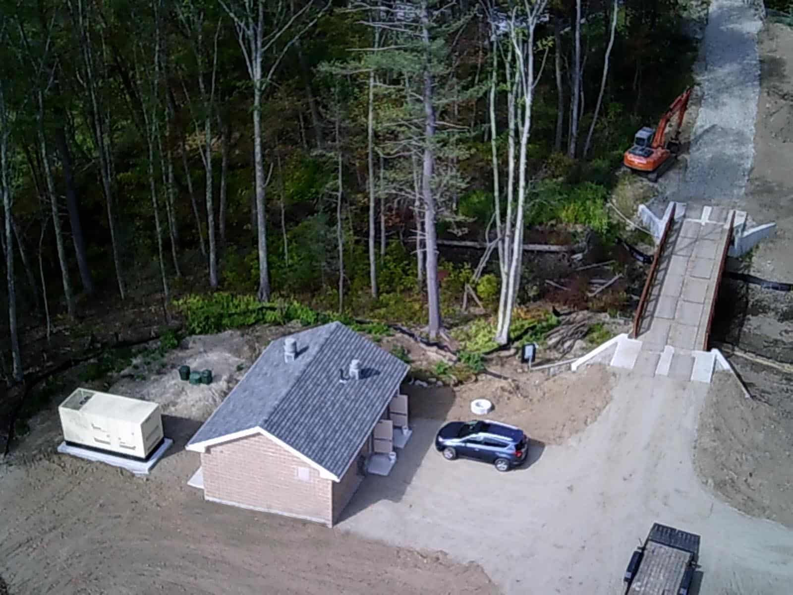
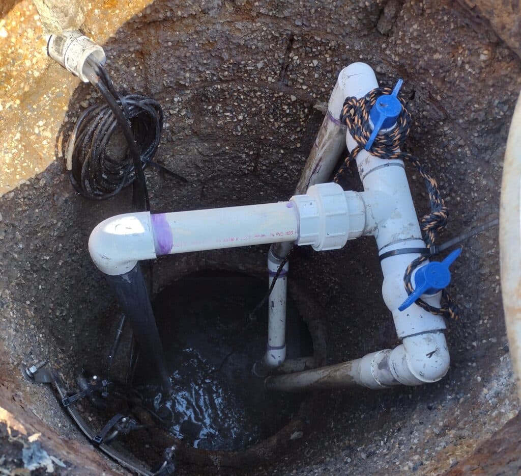 Final design development includes final design of the main pump station, remote pump stations, gravity sewers, force main, and low-pressure sewers for connection to the City of Danbury collection system including site plans, profiles of force main and gravity sewers, pump station structures and chambers, electrical and controls, emergency generators, odor control, erosion and control plans, etc. Also includes design of the main pump station building designed to match the local aesthetic and mask it as a non-utility structure.
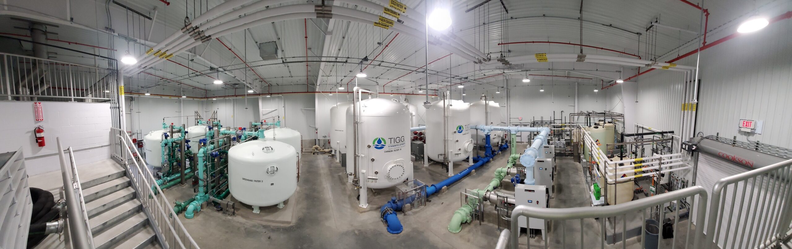
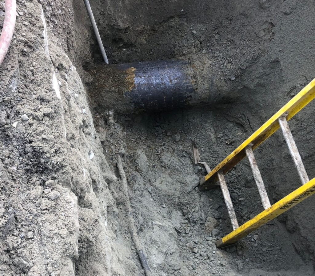 Design services included attending the kickoff meeting with City and reviewing existing information including tie-cards, the City’s existing GIS database that includes service material, and the City’s master list of services with service material.
 Construction Administration services for each phase included attendance at progress meetings and site visits, review of submittals, request for information, and purchasing change orders and payment applications. As-built record tie-cards were completed for each address and the master inventory of service material was updated as construction on each phase progressed.
  Replacement of the existing Thompson Corner Tank also served as the permanent action plan to address a Significant Deficiency outlined by the New Hampshire Department of Environmental Services (NHDES) in October 2020. The deficiency identified was severe deterioration of the coating on the inside and outside of the tank. NHDES required that funding be authorized by March 2022 and a tank construction contract be awarded by October 2022.
 And the Winner Is…
 Tata & Howard provided engineering services for permitting, design, and bidding of the Trinity Avenue Pump Station at the Trinity Avenue Wellfield (new source) and provided assistance with permitting, design, and reporting to the Massachusetts Department of Environmental Protection (MassDEP) for the proposed Trinity Avenue Well site.
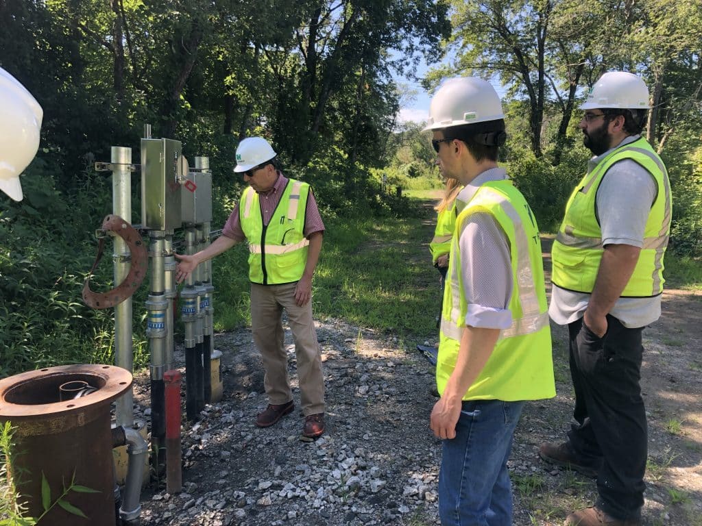
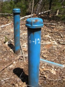 The property was owned by the Massachusetts Division of Fisheries and Wildlife (DFW), and the Grafton Water District swapped land with the DFW to obtain ownership and control of the Trinity Avenue site. Test wells were installed and short-term pump tests were completed on each of the wells. Based on the results of the tests, it was recommended to install a three well configuration of 18-inch x 12-inch gravel packed wells resulting in approximately 840 gallons per minute (gpm). The work under this contract included the completion of the Request for Site Exam and Pump Test Proposal for submission to MassDEP, installation and development of three (3) 18” x 12” gravel packed wells and pitless adapters, installation and development of approximately five 2-1/2” diameter observation wells, installation of two staff gages and piezometers, performing a five-day pump test, and collection and analysis of water quality.
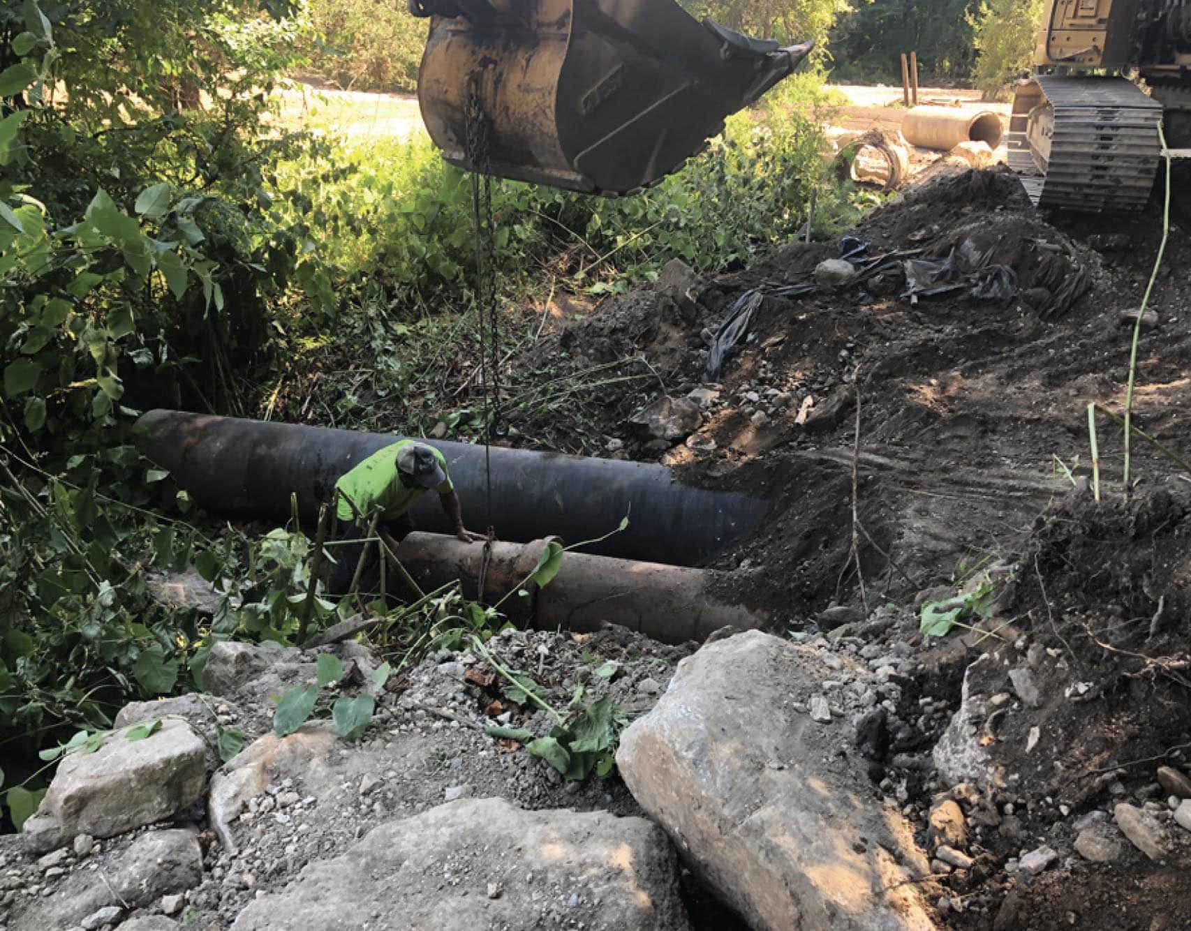
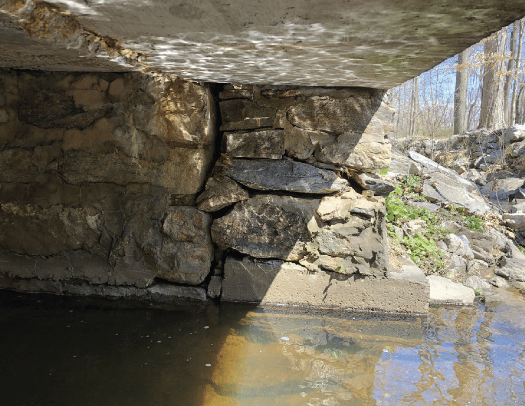
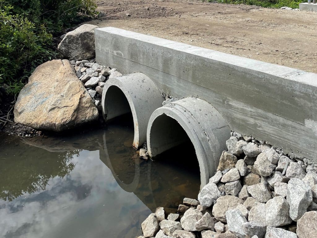
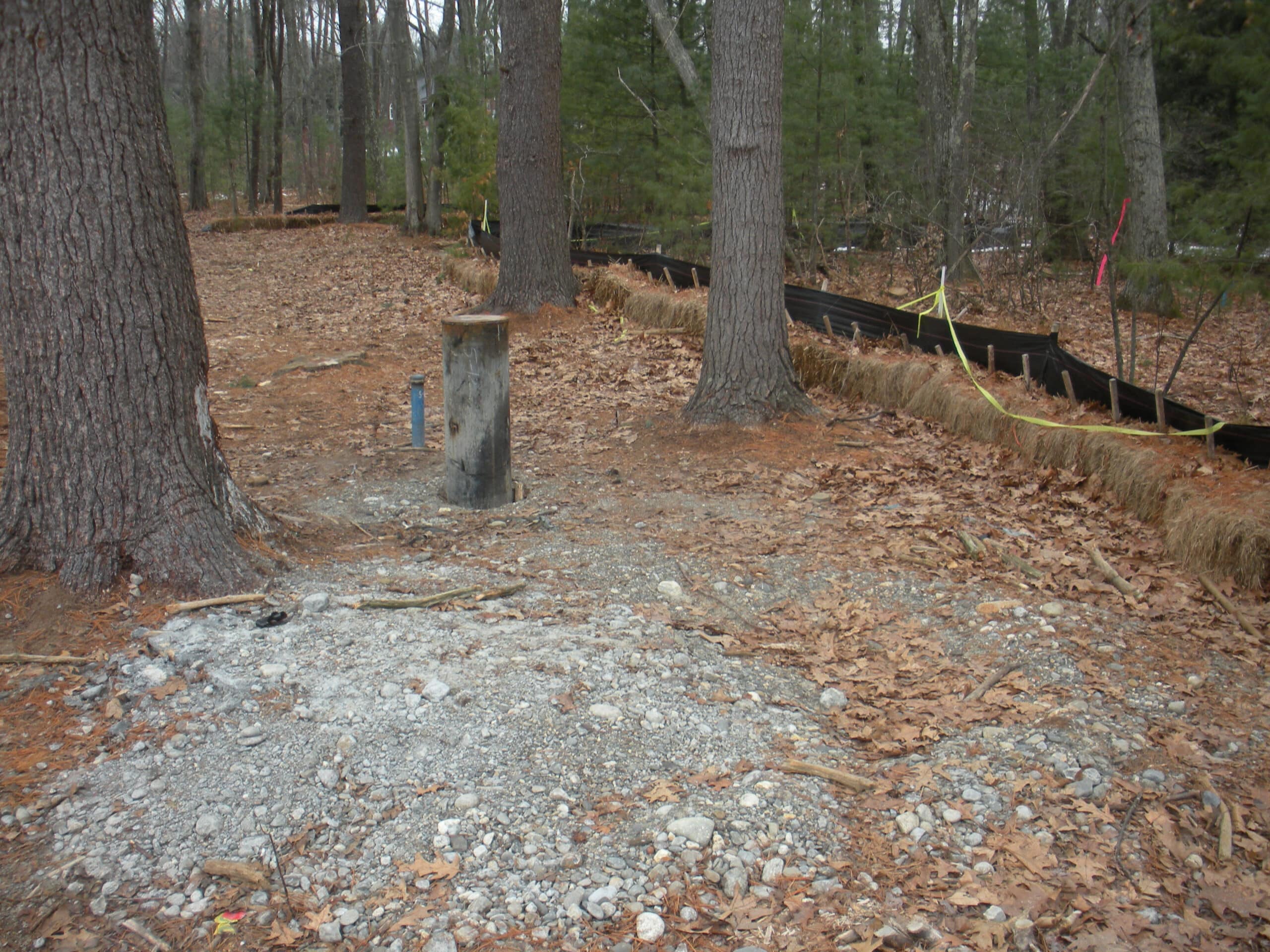 The project also included an evaluation of alternatives for the access road including installation of a bridge or an open bottomed culvert, and Tata & Howard assisted with the preparation of permanent easements for the installation of utilities and roadway to the well site. In addition, Tata & Howard prepared and submitted an NOI to the Grafon Conservation Commission.
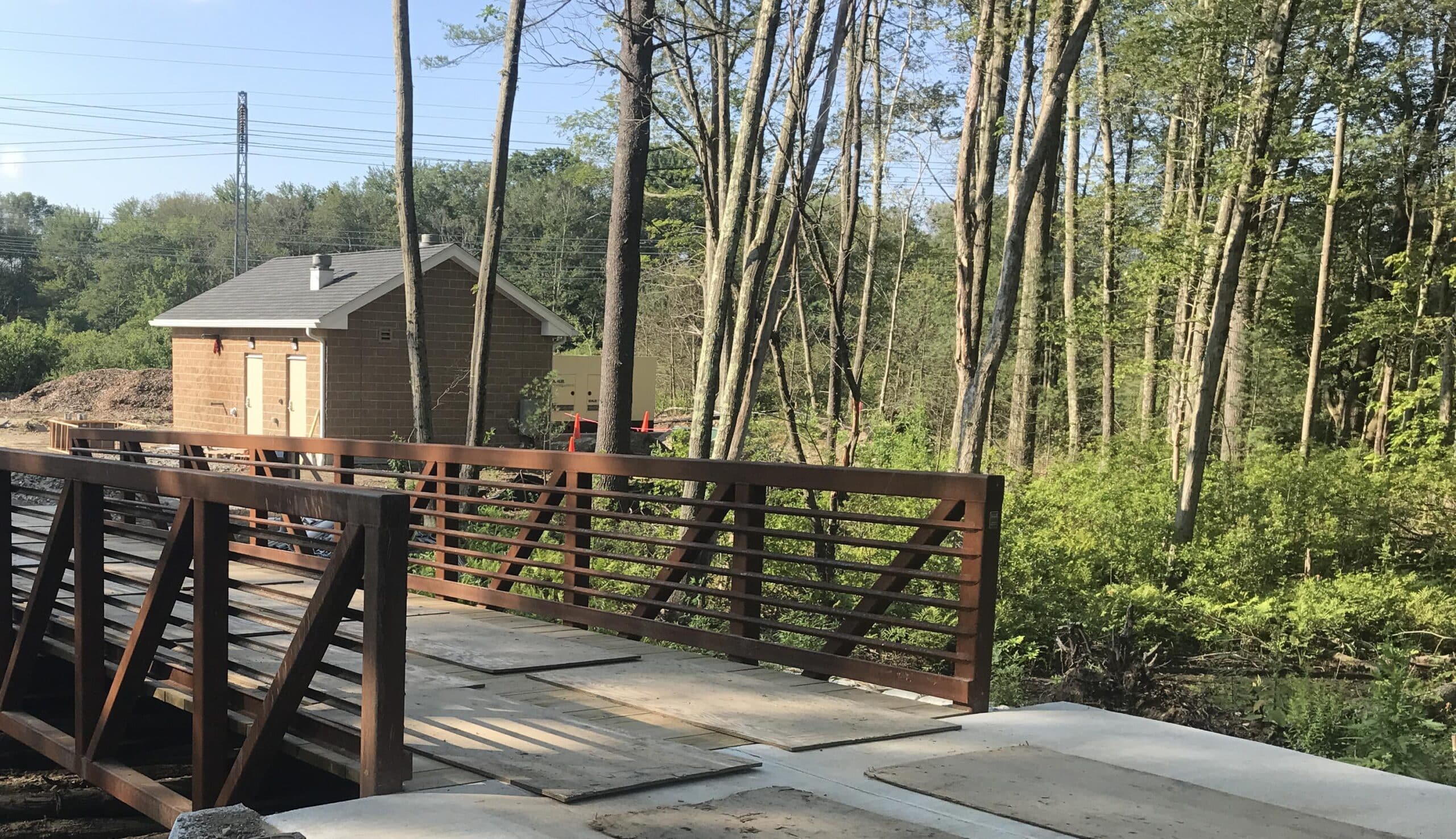
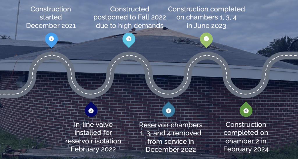 Following a review of the challenges, the design scope was revised. Final design and bidding on the project included standpipe rehabilitation, effluent valve and piping replacement, drain valve replacement, check valve replacement, and asphalt shingle roof replacement as well as the standpipe cover and man-way, interior lighting improvements, and instrumentation.


 A PFAS Journey to Determine Effective Management and Treatment Options
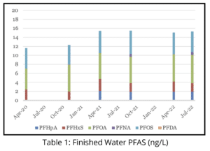 Currently, the Town has been managing the sources to improve water quality and stay under the current MCL of 20 ng/L for PFAS6. A mass balance is utilized to estimate finished water PFAS concentrations based on updated sample results and changes in the operation of the sources. Tata & Howard created the base tool which can be used to see how changes to PFAS levels or flow rates can affect the finished water concentration.
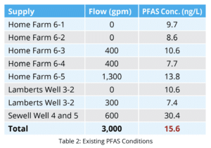
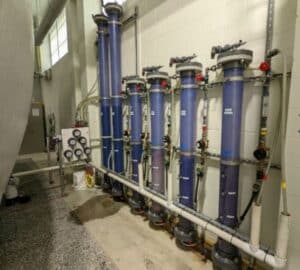
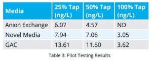 Table 3 shows the result from the different taps at the end of the pilot.
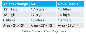 Table 4 is a summary as to what the permanent filter system may look like. The filters are similar in size but the number of recommended filters differs for each resin. The overall building footprint is similar as well. The anion exchange did perform slightly better than the novel media, however, the overall PFAS removal results over the duration of the pilot was similar. Because of this, construction costs, long term media replacement costs, and operational considerations were included as part of the media selection process.