While Emergency Response Plans (ERPs) are mandated by the EPA for most water supplies, the reality is that an ERP is a critical component whether mandated or not. The goal of an ERP is to guide and assist a water utility through emergencies, natural disasters, and articulated terrorist acts, and the intent is to present a methodical, sequential process to identify, investigate, and respond to an emergency.
ERPs are divided into two categories: Emergency Action Plans (EAPs) and Incident Specific Emergency Action Plans (ISEAPs). EAPs are broken down into five levels of emergency:
- Level I – Routine
- Level II – Minor
- Level III – Major
- Level IV – Natural Disaster
- Level V – Nuclear Disaster / Terrorist Threat
ISEAPs are designed to “RIP and RUN,” outlining a specific action plan response:
- Description of the event
- Facilities affected
- Initial notifications
- Response actions
- Follow-up actions
 Water District Background
Cherry Valley & Rochdale Water District (CVRWD) is in the Town of Leicester, Massachusetts. It was originated by a Legislative Act in 1910 and the current population served is 3,700. It is staffed by three operators who also act as a superintendent, clerk, and treasurer. The District receives water from Worcester, MA via an automated interconnection and an 8” transmission main supplying Cherry Valley service area and maintaining operational levels in Cherry Valley storage tanks. Water is conveyed through 8-inch transmission mains from the booster pump station to supply the Rochdale service area and to sustain operational levels in the Greenville water storage tank.
While the transmission main route through the Cherry Valley service area is mainly public roads, most of the transmission mains servicing the Rochdale service area are through wetlands.
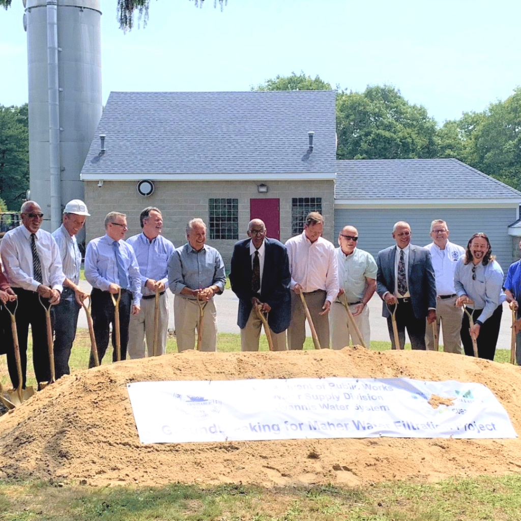
The Incident
The CVRWD suffered an incident on Sunday, October 27 in which the District’s ERP came into effect. At 3:30am, the On-Call Operator received a Low Water Storage Tank Alarm at the Greenville Water Tank. The Operator immediately notified the Superintendent. They compared SCADA trends of Greenville and Cherry Valley Tanks to confirm the alarm was for the Greenville Tank and that normal operational levels remained at the Cherry Valley Tank. At this point, they believed there was a leak in the Rochdale service area.
 Sunday, October 27, 3:30am: Response and Notifications
- Performed leak detection survey from booster pump station towards Rochdale service area, sounding a combination of hydrants and gate valves
- Sounded triple gate just prior to the transmission main reentering the wetland and got a hit
- Superintendent called first of the emergency contractors, Hydra Tech, to respond and stage at the Town’s Highway Department
- Contacted Prowler Leak Detection Services to conduct a survey to pinpoint the leak
- Continued to monitor the Greenville Tank level to confirm that Rochdale service area maintained positive pressure
- Worked to pinpoint the leak while the Superintendent expanded the notifications
- Superintendent of the Leicester Water Supply District (LWSD) discussed establishing a hydrant-to-hydrant (H-T-H) interconnection
- Contacted the Town of Leicester Emergency Manager with regard to the evacuation of a Critical Care Facility and Dialysis Facility
- Notified Leicester Fire Department to let them know that they had no use of hydrants in the Rochdale service area
- Contacted Leicester DPW for permission to use the highway yard to stage equipment
- Contacted EJ Prescott to deliver 300 feet of 2-inch water service line for H-T-H interconnection
- Contacted Leicester Con Com and explained the emergency and the need to enter wetlands to repair transmission main; permission was granted and they prepared to deliver the Emergency Certificate on Monday, October 28
- Superintendent contacted additional contractors to support operations
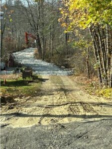 Sunday, October 27, 12:30pm: Wetland Road Construction
- Began constructing road into wetlands to access leak
- Road construction consisted of placement of 5’ x 18’ swamp mats which were covered with trap rock to allow construction equipment to build a 600-foot access road to leak location
- Construction crews worked through the night to complete the road
Sunday, October 27, 1pm: Interconnection/Notification
- Prior to activating H-T-H interconnection, contacted MassDEP (left message)
- Activated H-T-H interconnection
- Secured police detail to detour traffic
(2-inch water line temporarily ran on top of pavement through intersection) - Met with Emergency Manager and Deputy Fire Chief
- Issued a reverse 911 to all three water districts advising of emergency and urging residents to conserve water
- MassDEP called at 7pm, provided update, and agreed to call for another update the following morning (Monday)
- Leak detection and road building ongoing with difficulty pinpointing leak; believed the leak was further into the wetland than originally expected
- Correlation and road building went on through the night and into the next day
- Even with H-T-H interconnection, Greenville Tank dropped to an uncomfortable operational level
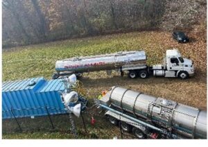 Monday, October 28: Tanker Shuttle
- T&H assisted with response and bulk tanker shuttle to fill the Greenville Tank
- Calls to tanker companies posted on the MassDEP approved list resulted in securing three tankers from two companies
- Booster pumping system had to be developed to fill Greenville Tank
- Contacted Rain-for–Rent for a 21,000-gallon transfer tank, pump, generator and 4-inch quick connect hose which allowed for two tankers to off-load into the transfer tank at the same time
- First day, two tankers operated 2pm-9pm
- Tankers refilled using designated hydrant in Cherry Valley service area and unloaded at Greenville Tank
- While tanker shuttle was in operation, MassDEP required bacteria and HPC samples from all approved coliform sample sites
- District required to maintain a 1.0 ppm chlorine residual at the tank during tanker shuttle
- Emergency light towers provided by Paxton and Holden Fire and Leicester Police Department
- Tanker shuttle ran for 3.5 days and delivered ~300,000 gal of water to Greenville Tank
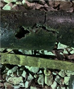
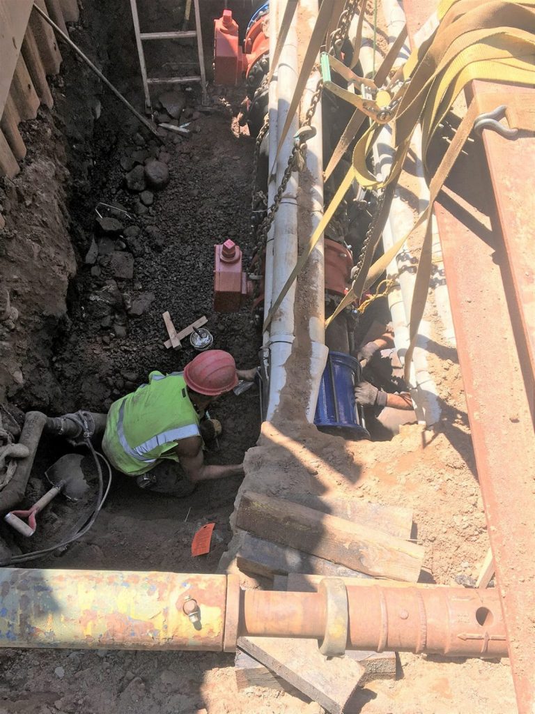
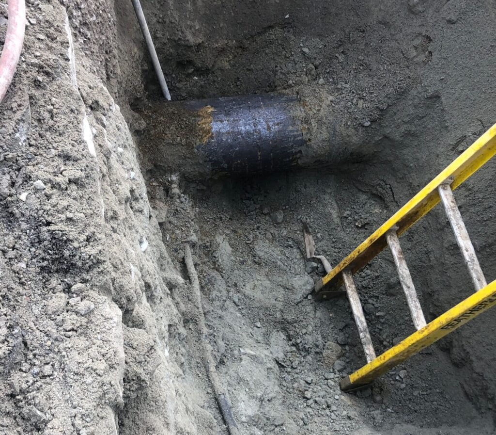
Tuesday, October 29, 12am: Repair/Return to Normal
- Leak located, excavated, and repaired
- Transmission main remained isolated and a tap was installed to allow for the addition of a sodium hypochlorite dosage of 300 mg/l
- Dosage remained in contact for 24 hours
- Main was flushed, water dechlorinated and sampled when achieved residual of 0.5 mg/l
- Samples collected and analyzed for bacteria and HPC
- All samples passed
Conclusion
The transmission main was back in service at 7:00am on November 1, and the total cost of the repair was $253,000.
There were some lessons learned from CVRWD’s emergency that the District plans to address for greater efficiency in the future:
- Design and install fixed piped interconnection between LWSD and CVRWD for future use instead of the H-T-H connection
- If necessary, start the Tanker Shuttle sooner
- Evaluate options for replacement of 8-inch transmission main from the Booster Pump Station to the Greenville Tank; select best option, design, secure funding, bid, and replace
All in all, the District’s ERP provided the roadmap for a rapid response, clear notification system, and timely repair.
Need help creating or updating your ERP or RRA? We can help! Contact us today.
 Tata & Howard is providing design and bidding of a treatment system for PFAS and PCE/TCE removal from three groundwater wells at the Kenosia Well Field.
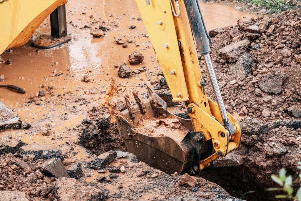 Tata & Howard was retained by the Town of Leverett for design and permitting engineering services to expand the Amherst water distribution system into the Town of Leverett.
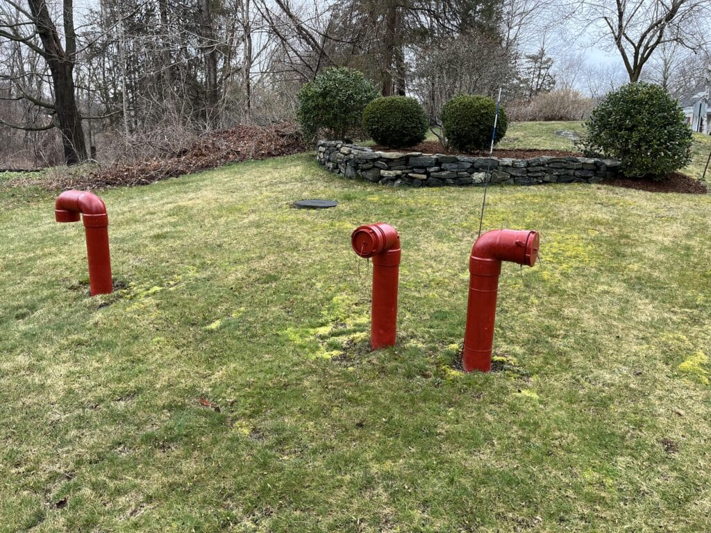 Estimated project budgetary costs for the sewer service area collection system, pump stations, and transport to the City of Danbury along with a phasing and implementation plan were included in the final draft report to the Town of New Fairfield.
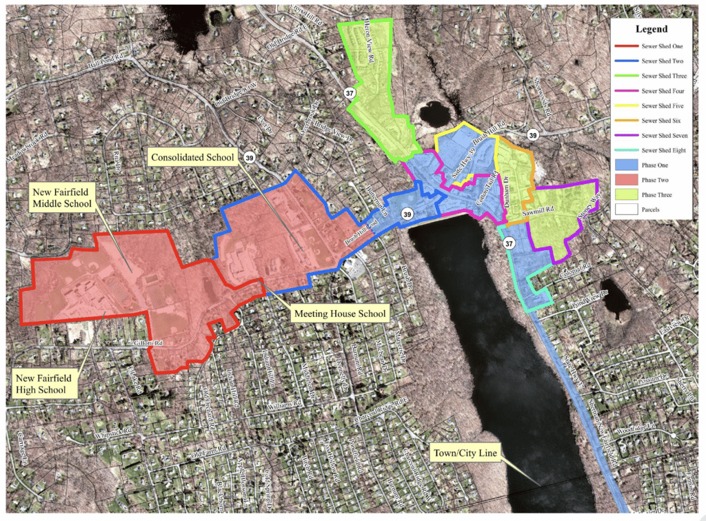 Tata & Howard provided preliminary and final design of 2.7 miles of gravity sewers, one main pump station, four remote, submersible pump stations, 2.3 miles of force mains, , and 4,000 linear feet of low pressure sewer. The project also includes identifying easements, land acquisition plans, preparation of permitting, and bidding assistance.
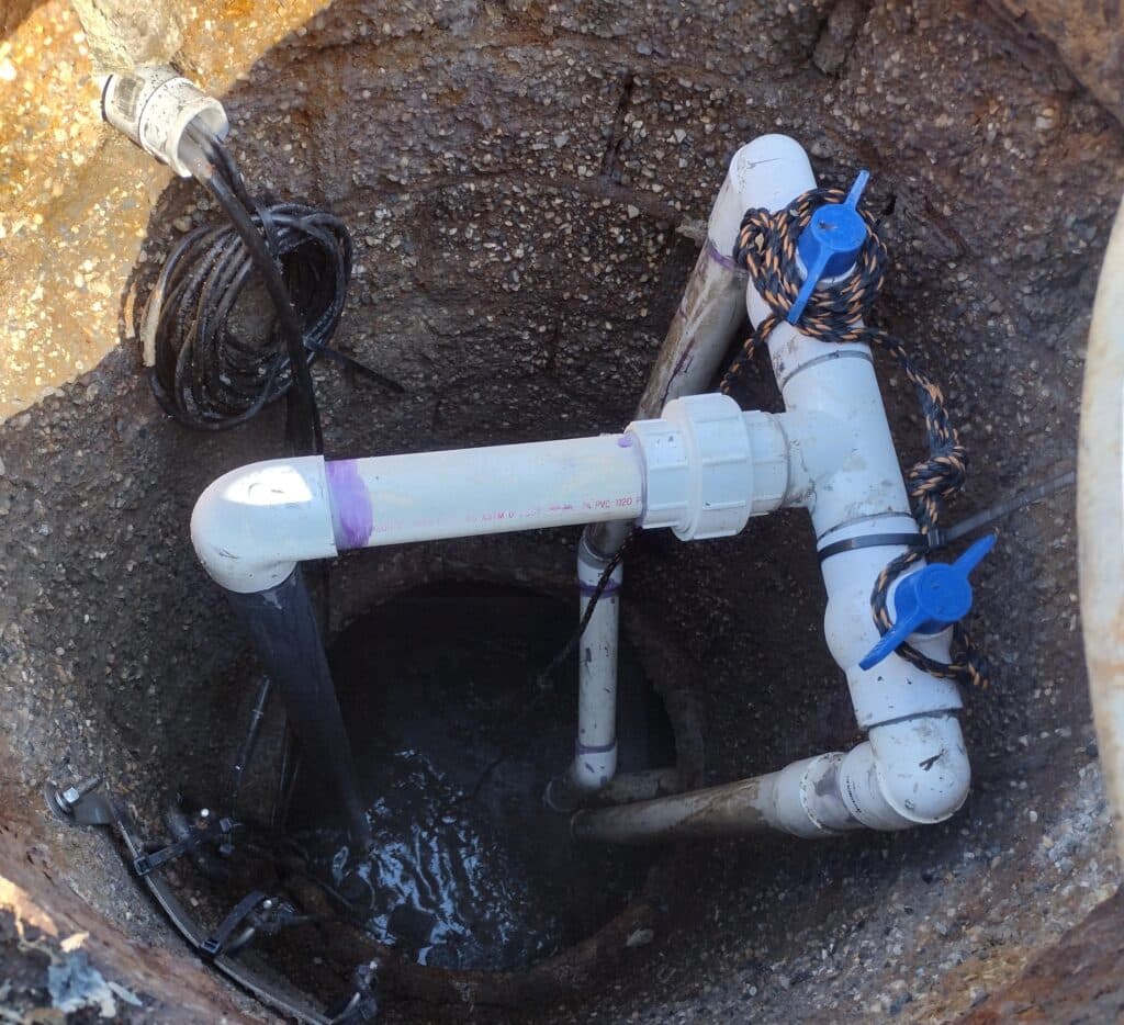 Final design development includes final design of the main pump station, remote pump stations, gravity sewers, force main, and low-pressure sewers for connection to the City of Danbury collection system including site plans, profiles of force main and gravity sewers, pump station structures and chambers, electrical and controls, emergency generators, odor control, erosion and control plans, etc. Also includes design of the main pump station building designed to match the local aesthetic and mask it as a non-utility structure.
 Design services included attending the kickoff meeting with City and reviewing existing information including tie-cards, the City’s existing GIS database that includes service material, and the City’s master list of services with service material.
 Construction Administration services for each phase included attendance at progress meetings and site visits, review of submittals, request for information, and purchasing change orders and payment applications. As-built record tie-cards were completed for each address and the master inventory of service material was updated as construction on each phase progressed.
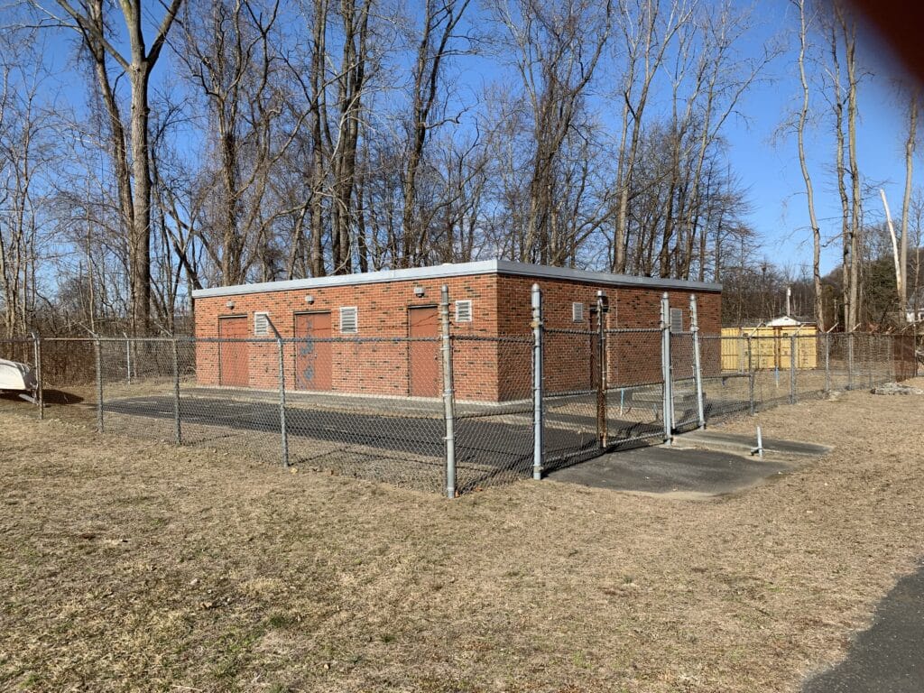
 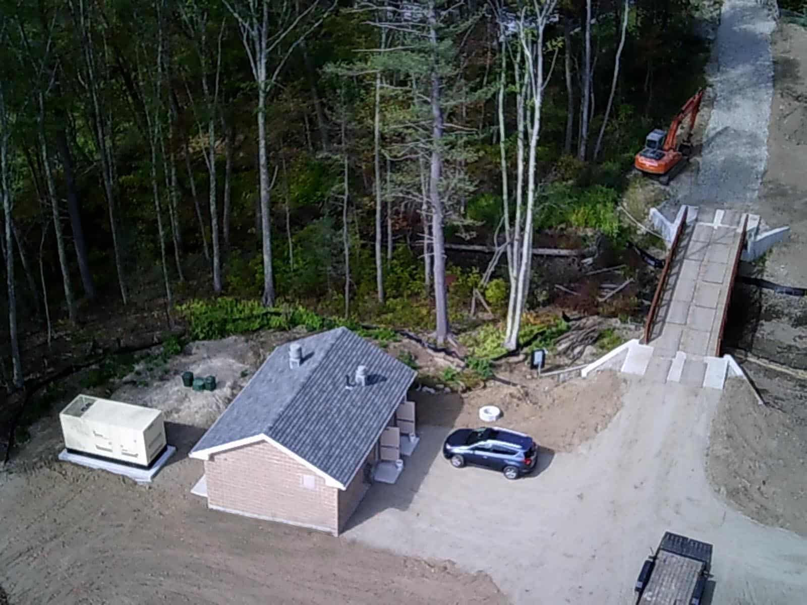 Tata & Howard provided engineering services for permitting, design, and bidding of the Trinity Avenue Pump Station at the Trinity Avenue Wellfield (new source) and provided assistance with permitting, design, and reporting to the Massachusetts Department of Environmental Protection (MassDEP) for the proposed Trinity Avenue Well site.
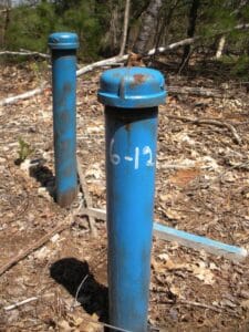 The property was owned by the Massachusetts Division of Fisheries and Wildlife (DFW), and the Grafton Water District swapped land with the DFW to obtain ownership and control of the Trinity Avenue site. Test wells were installed and short-term pump tests were completed on each of the wells. Based on the results of the tests, it was recommended to install a three well configuration of 18-inch x 12-inch gravel packed wells resulting in approximately 840 gallons per minute (gpm). The work under this contract included the completion of the Request for Site Exam and Pump Test Proposal for submission to MassDEP, installation and development of three (3) 18” x 12” gravel packed wells and pitless adapters, installation and development of approximately five 2-1/2” diameter observation wells, installation of two staff gages and piezometers, performing a five-day pump test, and collection and analysis of water quality.
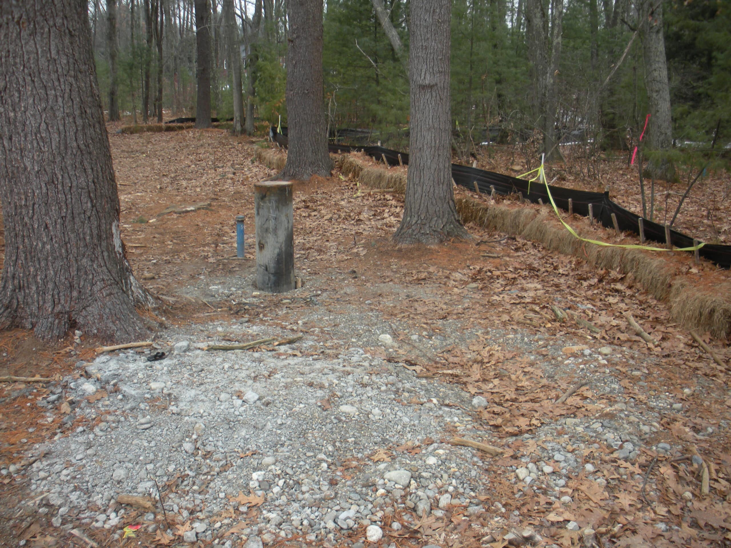 The project also included an evaluation of alternatives for the access road including installation of a bridge or an open bottomed culvert, and Tata & Howard assisted with the preparation of permanent easements for the installation of utilities and roadway to the well site. In addition, Tata & Howard prepared and submitted an NOI to the Grafon Conservation Commission.
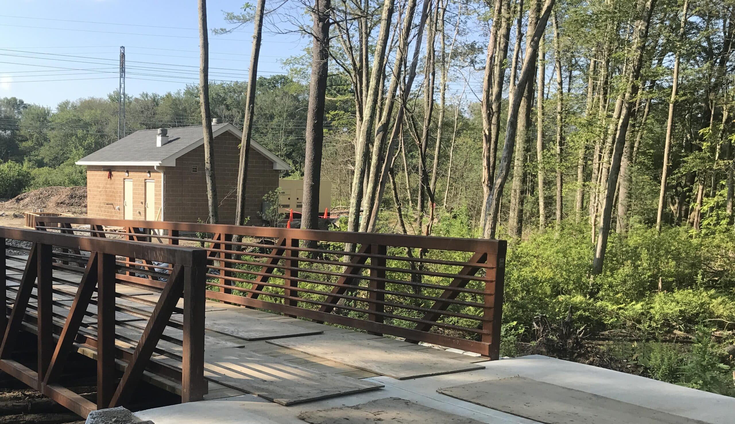
 Following a review of the challenges, the design scope was revised. Final design and bidding on the project included standpipe rehabilitation, effluent valve and piping replacement, drain valve replacement, check valve replacement, and asphalt shingle roof replacement as well as the standpipe cover and man-way, interior lighting improvements, and instrumentation.